Variable Speed Pumping
We have been looking into variable speed pumping for some time now. There seem to be obvious benefits from varying the speed of the collector pump based on the radiation level hitting the collectors, as indicated by the collector output temperature. During marginal radiation, a constant flow system may cut on and off repeatedly. The start/stop cycling is called short cycling. The system collects little energy and just wears out the pump.
Some controller manufacturers try to minimize short cycling by having a 5 minute delay in startup/shutdown times. The idea is to have the system ride through the morning radiation ramp up, or short (5 min) rain bursts, or cloud coverage, thus preventing short cycling. At a minimum, it prevents short cycling any faster than 5 minutes.
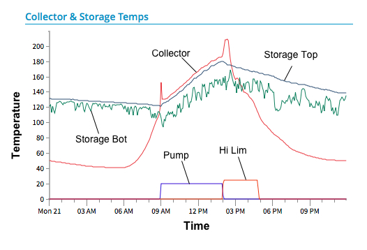
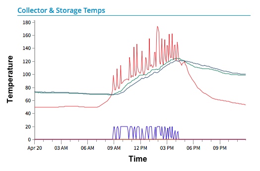
Figure 1 shows a constant speed pump on a sunny day, and fig. 2 shows a constant speed pump cycling on and off on a very marginal day. The blue line at the bottom of each graph is the pump runtime and the red line in fig. 1 indicates high limit shutdown when the tank reaches 180ºF. Each data point represents a 5 minute average value.
Reducing the collector flow during low radiation allows the system to continue running and producing (reduced) energy. We see these conditions daily on our monitored systems. Variable speed pumping will not prevent all short cycling, but it can minimize it. It can also extend the run time at the beginning and the end of every day.
To change the speed of a pump, a special electronic driver unit, called a Variable Frequency Drive (VFD) is used to power the pump. The growing availability of Variable Frequency Drive units is likely to cause an increase in their use in solar systems, and some pump manufacturers are beginning to build VFDs on the side of their pumps. However, most built-in VDFs are on small pumps, which are not well suited to large commercial systems.
There are reasons to separate the VFD from the pump. Vibration, heat, and electrical interference are some of them. Most VFDs are located with other controls in a separate control panel.
VFDs are sized and priced according to the power and voltage of the pump motor. The units come in single phase input/output, single phase input/three phase output, or three phase input/output. The input and output voltages can vary from 110 to 440vac.
A specific type motor is required to work with a VFD. Ordinary shaded pole and permanent spit capacitor types may work, but other motor types may not. As the name implies, the VFD varies the frequency of the AC power going to the motor. In our tests, we have run pumps from 100% (60Hz) down to 30% (18Hz). Different pumps have different lower limits.
There are also permanent magnet DC motors with variable speed controllers. In this article, we focus on VFDs for AC motors, which are the most common type used in solar systems.
The components of a variable speed solar pumping system include
- dT Control: Typical solar controllers monitor the collector and storage tank temperatures and calculate the temperature difference (called delta T, or dT). They turn a relay on and off in response to the cut-on and cut-off temperatures differentials. However, typical solar dT controllers do not provide an output signal that can run a VFD.
- Voltage Ramp: VFDs require a voltage signal that represents the delta T between the collector and storage. As the temperature difference goes up, the pump speeds up. As it falls, the pump slows down. Usually the ramp signal is a straight line representing speed vs dT. However, any line shape, such as an exponential, or simple steps, could be programmed to vary the speed of the pump. The dT controller must have a variable output voltage signal to drive a VFD.
- VFD driver: The VFD driver receives the voltage ramp from the controller and varies the frequency of the AC power going to the pump. VFDs have a non trivial amount of programming needed to set them up properly. There may be as many as 50 settings to control startup current, ramp up speed, scaling of input signals, max and min operating speeds, response times, etc. The learning curve to properly program a VFD can be significant.
The first step is to get a dT controller that can supply a voltage ramp for the VFD. We developed two systems that can control VFDs.
One is called a CMR system (Control, Monitor, Report) that controls the solar dT functions, collects data from 5 temp sensors and one flow sensor, calculates all the control logic, energy, and flow values, and sends the data to our web hosting site. The CMR system comes in two flavors, wireless and LAN. (See http://cmr.holocene-energy.com/demo/systems for a tour of the wireless cloud web hosting program).
The other device is a simple solar controller programmed to run up to two dT systems (collector and pool loops, for example). It outputs two voltage ramps for two VFDs .
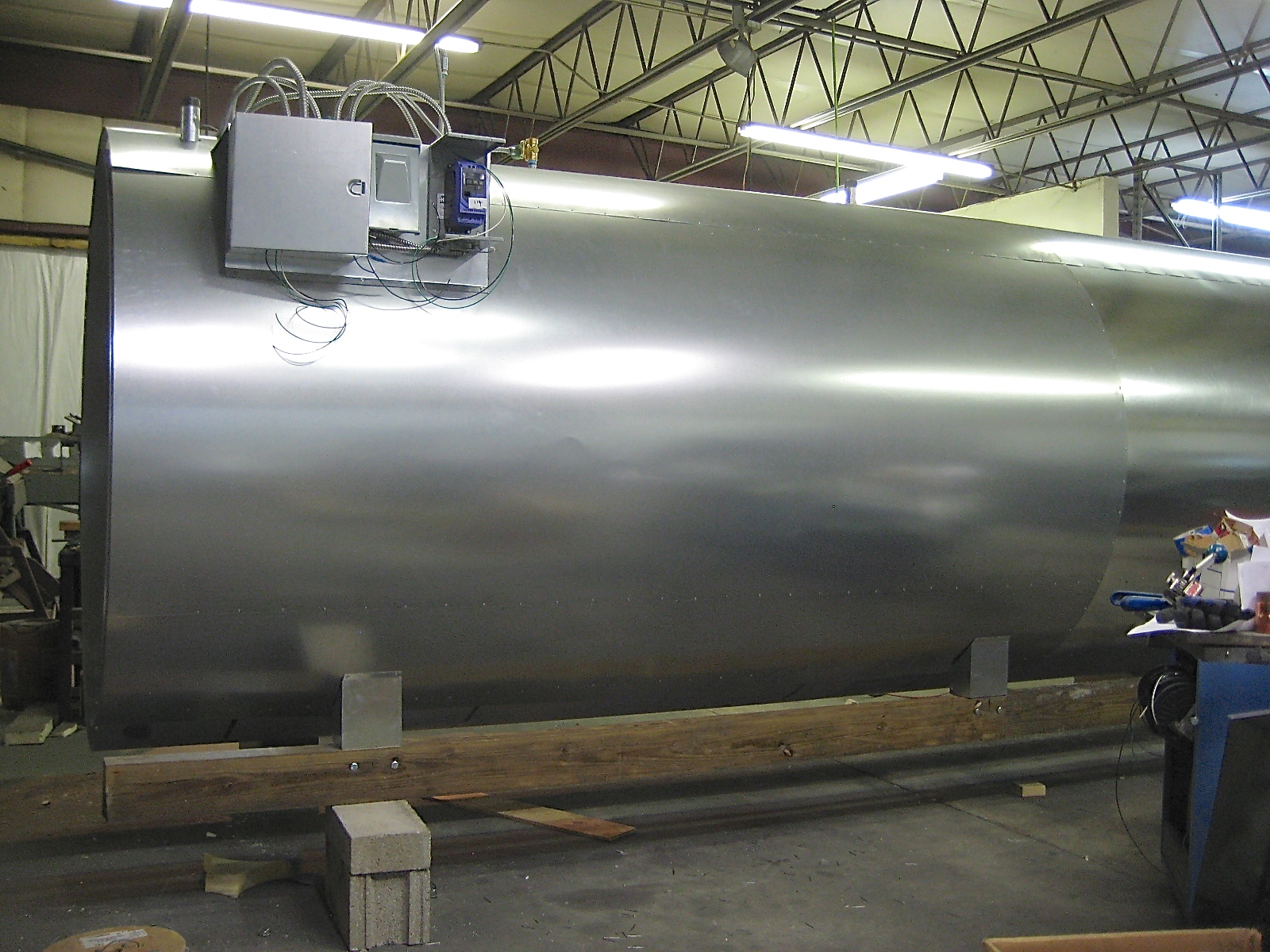
Figure 3 is a photo of a 2500 gallon system with a VFD (blue) installed on the right end of the controls.
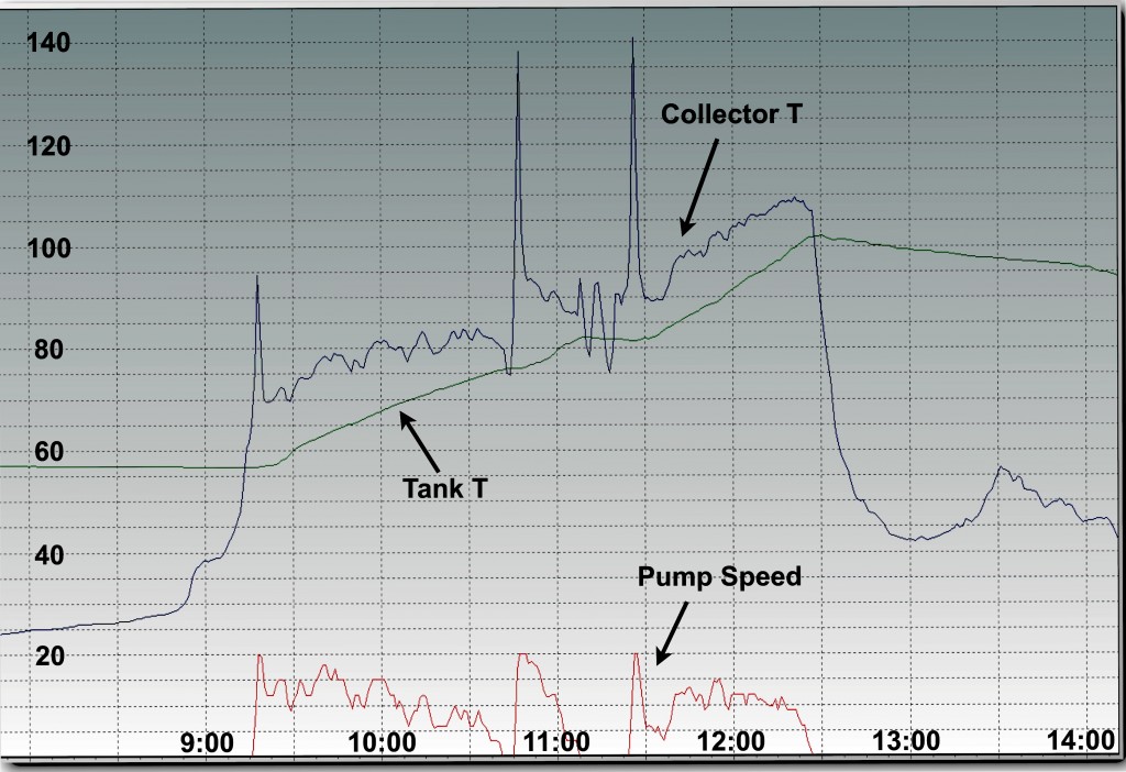
The results can be seen in the graph of fig. 4. showing the operation of the system on a winter day after installation in Massachusetts. The collector temperature starts at about 27F at dawn and rises to 95F by 9:20am when the pump cuts on at full speed (= 20 on the scale).
The tank water temperature of 57F chills the collectors down rapidly and the pump slows to maintain a positive heat gain. The radiation level then begins to fall with the pump running slower and slower, until it finally cuts off about 10:45am.
The empty collectors heat up rapidly again and the system turns back on, but the solar radiation continues to fall, shutting the system off about 11:10am. At 11:25am the sun comes out and the system starts again, running to the end of the solar day at 12:30 pm, when a cold weather front moves in and radiation levels remain low.
Over the run time of 3 hours and 10 minutes, the tank gained 46ºF, which added about 950,000 Btu to the tank. The average pump speed was perhaps 50-60% of max during the run time. This calculation does not take into account any energy that may have been removed from the tank, so the total energy produced could be much higher.
In summary, the results show that a VFD system can significantly increase the solar energy collected under low radiation conditions. Determining whether a VFD system is worth the cost and effort is dependent on the climate where the system will be installed. A sunny climate may see little overall benefit. A cloudy climate will see the best results.
The components are not commonly available, so building a VFD control system can involve a significant learning process. In addition, pump manufacturers may not endorse running their pumps at slower speeds. The concern is that a reduced flow may cause overheating of the pump volute bearings, causing either leaks or seizing. One major pump manufacturer I spoke with is still studying the question. It would be wise to check with the pump manufacturer to be sure their pumps are suitable for VFD operation.


