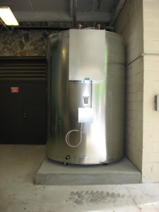
Optimal System Thermodynamics

New FHS @ Duke University
In this blog post, I’d like to share some information about the Fluid Handling System design, especially relating to the immersion vent and the function of the cavity.
Let me give you a little background into the origins of the Fluid Handling System design that dates back to 1978. At that time I undertook a technical analysis of existing solar themal designs and noted many problems with pressurized glycol systems, particularly compromised efficiency, high maintenance, and many failure modes. I will not go into all the details of that analysis, but the result was a list of parameters I thought a well designed solar thermal system should have. They included:
- No pressurized glycol with expansion tanks
- No pressure vessels
- No pressure relief valves
- No air vents
- No check valves.
These items did nothing for performance, they only contributed to high maintenance and lower thermal efficiency.
I wanted optimal system thermodynamics. By this is meant that every part of the system should have minimum parts, maximum efficiency, and maximum energy conservation.
Let me skip to the results, which have been proven since 1978, with many systems still running well after 30 years. The basis of the system design, trade named the Fluid Handling System (FHS), is a non-pressurized storage vessel, using only corrosion inhibited water, and no heat exchanger between the collectors and the tank. The tank has an air gap at the top that increases when water is drawn from the tank.
A simple vent could lead to large evaporative losses, so a unique design was originated, called the immersion vent. It is a pipe that runs upward through the face of the tank and into the air gap at the top. There is a temperature gradiant inside the pipe that increases from bottom to top. Therefore, a molecule of air at the bottom of the vent tends to rise with warming into the tank. No air tends to flow downward out of the vent. This action prevents evaporative loss of water from the tank.
The vent also allows the tank to breathe when the total air volume inside changes with temperature. This allows a small amount of water to escape. There can also be occasional steaming on startup when the tank is hot. The steam is also relieved by the vent. A make up water system is an option to keep the tank full. The immersionvent is part of the patent on the FHS.
A second very important feature is the insulated cavity on the front of the tank. All the fittings on the face of the tank are inside the cavity, which is surrounded by insulation, with an insulated door. On conventional systems, these components are frequently left exposed, wasting significant amounts of heat into the equipment room. In a FHS, these sources of heat loss are all inside the insulated cavity, minimizing heat loss. Only air-cooled pumps are outside the cavity. This feature is also part of the system patent.
I hope this explanation answers some of the questions out there among my readers. Please feel free to leave a comment below if you have questions or thoughts you would like to share.
Until next time!
Dr. Ben

Sketch, please?
Kevin, what would you like a sketch of?
Dear Dr. Ben,
Once again I thank you for your very useful detail of drain back system. You’re right to make a huge effort to advertise the benefits of drain back system.
My 30 years experience in the solar thermal system using glycol for the closed loop and the problem of lowering PH of glycol when there is a stagnation condition make me to appreciate your information.
Drain back system is suitable for very cold and very hot climates too.
To make our systems more reliable we have made a differential controller that appears faults on the display and voice alarm in case of system failure. The attached file shows you the most significant parameters of the controller. However a new design follows where the controller will be rail- mounted and the whole width will be as the width of three rail-mounted fuses namely 54 mm (2.12”). The controller later will be combined with an SMS telephone controller. The software is ready but I will be very grateful if you could suggest us some operations that have to be added too.
Thank you again for your valuable information
C. Oikonomidis
Civil Engineer M.Eng.
oikon@hol.gr
I think you have done a good job of thinking up the major failures that could occur. You want to detect out of range values on the sensors (short and open circuits) and a stuck pump. However, determining when the pump is stuck can be tricky.
You are using a high temperature reading on the collectors to indicated the pump is not pumping. There are several reasons the pump could not be pumping.
1) the high limit temperature in the solar tank has been reached and the pump turned off
2) the pump rotor is jammed
3) the power wiring to the pump is open circuit because of a fault
4) the power service to the building is off. In this case the whole controller is off and you can’t signal an alarm.
So, the reasons the pump is not pumping are varied and one of them is a normal operating mode. You need a way to distinguish these different modes from each other.